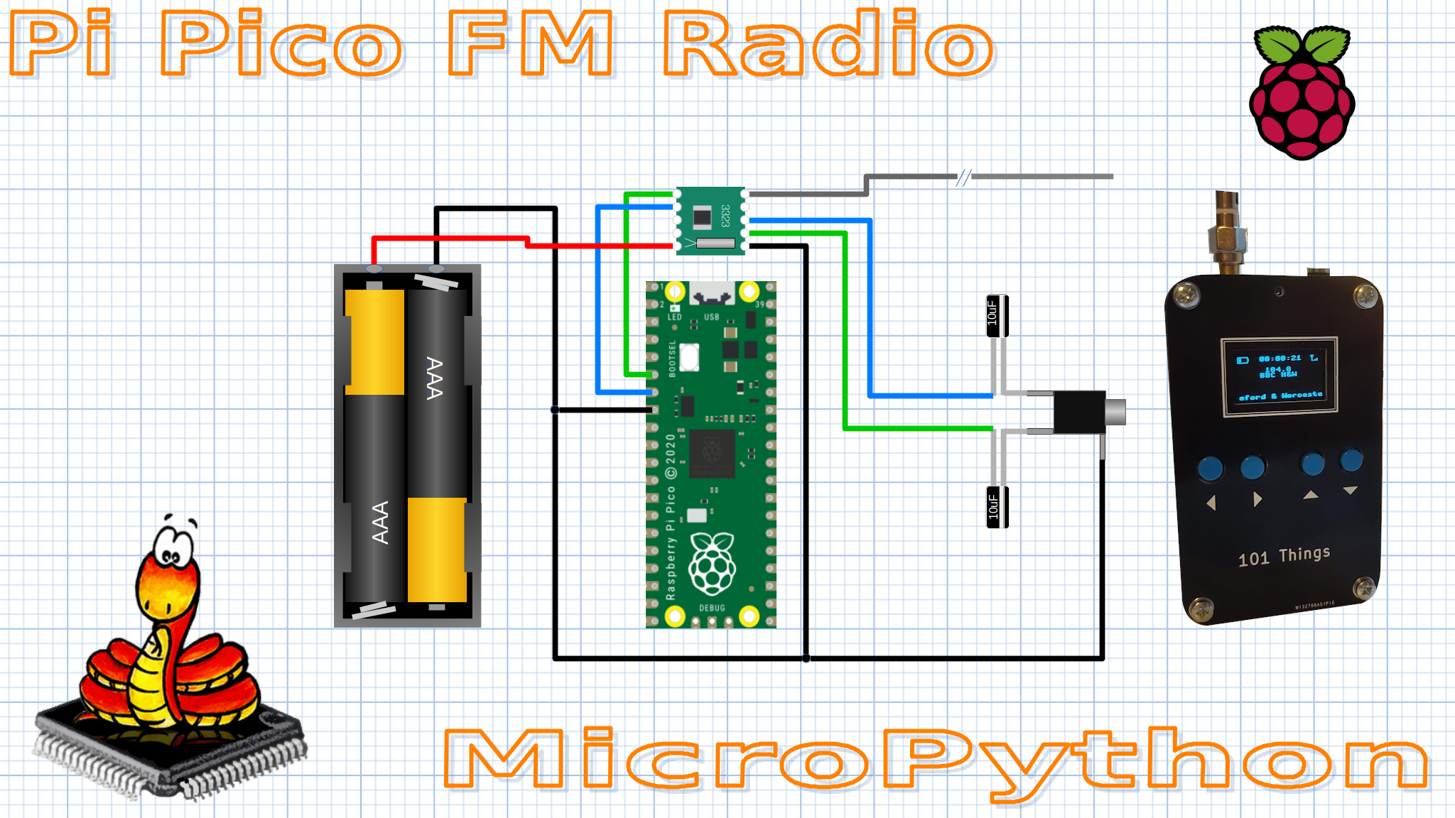
FM Radio using RDA5807M and MicroPython
Quick Links
If you want to give it a go, you can find the code here: FM Radio Code
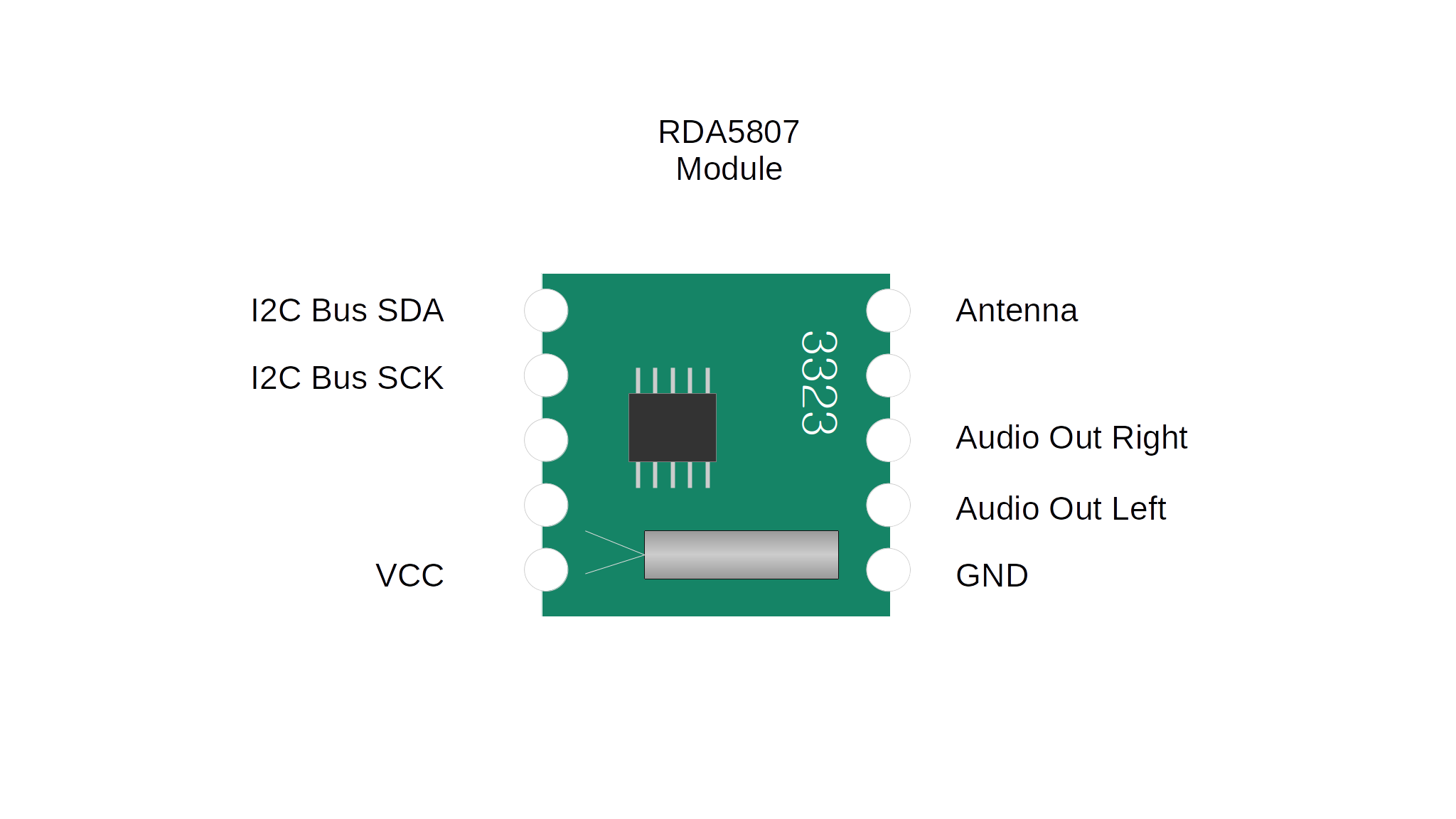
RDA5807M
The RDA5807M is a highly integrated single-chip FM stereo radio tuner. The chip can be connected to a microcontroller using the I2C interface to control it. It includes everything you need to add an FM radio capability to a microcontroller project with only a couple of extra components. It can even directly drive a 32 ohm load (e.g. headphones) without using an external amplifier. There is a plentiful supply of very cheap modules based on this chip that make it easy to design an FM radio or to add an FM radio to another project.
Apart from the chip itself, they include a crystal oscillator and a couple of capacitors, but not much else. The modules aren’t a standard pitch, ideally, they would be soldered to a suitable PCB footprint, but with a bit of care, you can solder small wires to the pads. The pads are quite delicate and can easily fall off, so it is important to relieve any strain on the wires.
The interface is very simple, it just needs power, an I2C connection, an antenna input and audio output to be connected.
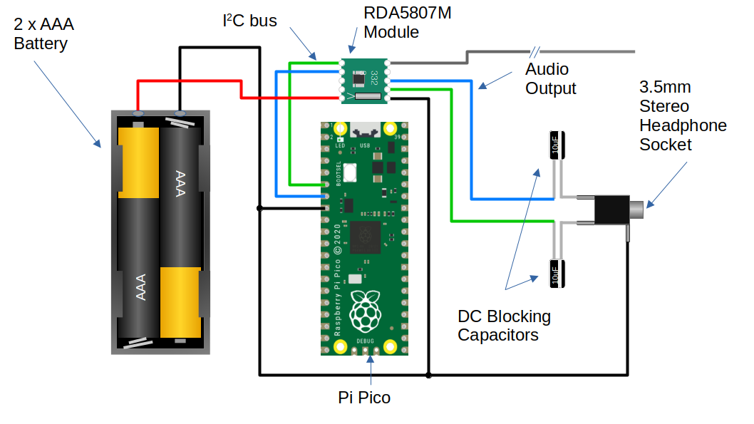
Breadboard Version
To put the RDA5807M module through its paces I built a simple “breadboard” FM receiver using a Pi-Pico. It doesn’t have a dedicated user interface, I’m using a USB-serial connection to control the tuning and the volume.
Parts List
Most parts are commonly available and could be purchased from multiple sources, but I have included links to some example components.
1x 3.5mm stereo headphone socket
2x 10uF electrolytic capacitor
1x Battery holder 2xAA or 2xAAA
MicroPython Library
This time, I thought it would be fun to build the project using MicroPython. The RDA5807M is doing all the work, so there’s no need to squeeze every ounce of performance out of the device, so why not enjoy the power and simplicity of a Python programming environment?
I wrote a simple Python library to control the RDA5807M using MicroPython’s built-in I2C library. The Pi-Pico has hardware support for I2C if you use the dedicated pins. This is the preferred option for I2C control, but it is possible to use pretty much any pin using the software I2C implementation in MicroPython. The interface to both hardware and software I2C is the same, so the RDA5807 library works just as well with either.
Antenna
For the antenna, I just connected 750 mm of wire to the antenna pin of the module to form a simple whip.
Headphones
The module is capable of directly driving a 32-ohm load, so we can drive a pair of headphones without any additional amplification. I just added a couple of 10uF DC blocking capacitors and a 3.5mm stereo socket.
PSU Noise
The RDA5807 does need a low-noise PSU. The Pi-Pico uses a switched-mode voltage regulator to drive the 3.3v rail. The regulator automatically switches to a power-saving mode when it is lightly loaded. Unfortunately, the regulator has a great deal of ripple when operating in this mode. It is possible to override the power-saving feature of the regulator by setting the GPIO23 output high. It is worth doing this in any application that might be sensitive to PSU noise. Unfortunately, even after disabling the power-saving mode the 3.3v output from the Pi-Pico still had too much noise for the RDA5807M and it wouldn’t receive any stations. For simplicity, I used 2 AA batteries to provide a low-noise power supply to the module. This worked great and the radio worked well.
USB Serial Example
I knocked up some simple example code to test out the radio using the USB serial port to control the device.
import sys
import time
import rda5807
from machine import Pin, I2C

#disable power save mode to reduce regulator noise
psu_mode = Pin(23, Pin.OUT)
psu_mode.value(1)

# configure radio module
radio_i2c=I2C(0, sda=Pin(4), scl=Pin(5), freq=400000)
radio = rda5807.Radio(radio_i2c)
time.sleep_ms(1000)

volume = 1
mute = False
frequency = 88.0

radio.set_volume(volume)
radio.set_frequency_MHz(frequency)
radio.mute(mute)

print("Pi Pico RDA5807 FM Radio Example")
print("press ? for help")
while(1):
    command = sys.stdin.read(1)
    if command == "?":
        print("Commands")
        print("========")
        print("")
        print("? - help (this message)")
        print(", - seek down")
        print(". - seek up")
        print("- - volume down")
        print("= - volume up")
        print("")
    if command == ".":
        print("seeking...")
        radio.seek_up()
        frequency = radio.get_frequency_MHz()
        print(frequency, "MHz")
    elif command == ",":
        print("seeking...")
        radio.seek_down()
        frequency = radio.get_frequency_MHz()
        print(frequency, "MHz")
    elif command == "=":
        if mute == True:
            mute = False
            radio.mute(mute)
        elif volume < 15:
            volume += 1
            radio.set_volume(volume)
    elif command == "-":
        if volume > 0:
            volume -= 1
            radio.set_volume(volume)
        elif mute == False:
            mute = True
            radio.mute(mute)
    time.sleep_ms(100)
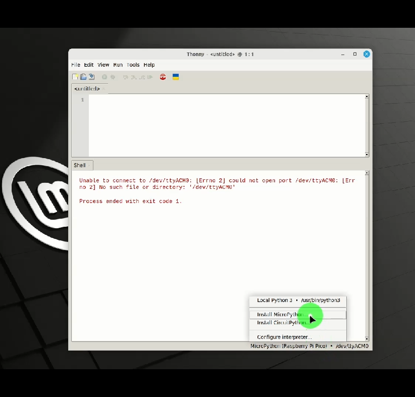
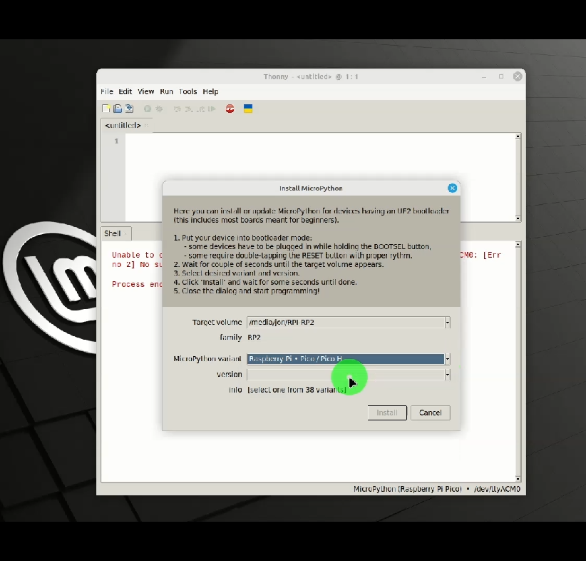
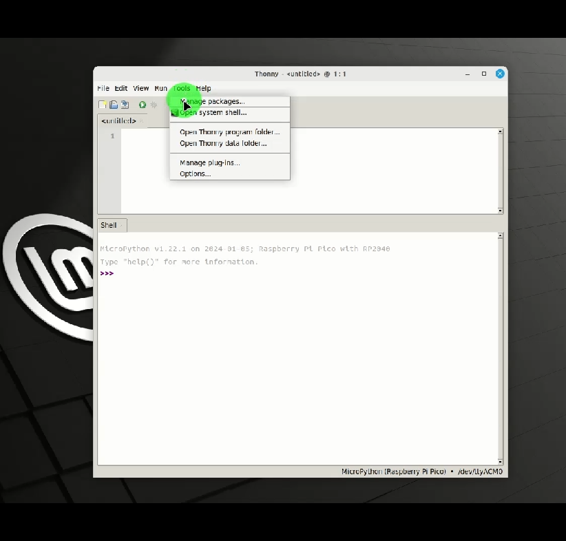
Installing Thonny and Micropython
Thonny is one of the easiest tools to get started with MicroPython development on the Pi-Pico. Details about how to download and install Thonny can be found here. Once Thonny has been installed, installing Micropython on the Pi-Pico is a simple operation.
Trying the serial example
By default, micropython will load and run the module called main.py in the root folder. Loading the example is simply a matter of transferring serial_example.py to the Pi-Pico, renaming it to main.py. You also need to transfer the rda5807.py. You can do this using Thonny, which also provides the ability to edit, run and debug the script or drop into the MicroPython interpreter. For convenience, I also added a simple script to transfer the necessary Python files to the Pi-Pico. It makes use of the pyboard.py utility to transfer the files to the Pi-Pico’s flash-based file system. You may need to edit the serial port settings in the send_serial_exampl_to_pico script to match the serial port names on your system.
$cd 101Things/19_fm_radio/
$. send_serial_example_to_pico
Once the Python modules are loaded, the example code is automatically loaded when the Pi-Pico boots. You can connect to the USB serial port using the screen utility, or another serial terminal application. The serial example uses simple commands to tune a station or adjust the volume.
$screen /dev/ttyACM0
Commands
========

? - help (this message)
, - seek down
. - seek up
- - volume down
= - volume up
seeking...
104.0 MHz
seeking...
106.7 MHz
seeking...
102.8 MHz
Standalone Version
Now we have the radio functionality, we can think about building a standalone radio. There is lots of room for customisation, there is plenty of scope to experiment with the user interface, to make a portable device or perhaps a retro-style radio. Perhaps this could be combined into another project, adding FM radio functionality to an MP3 player, or an internet radio?
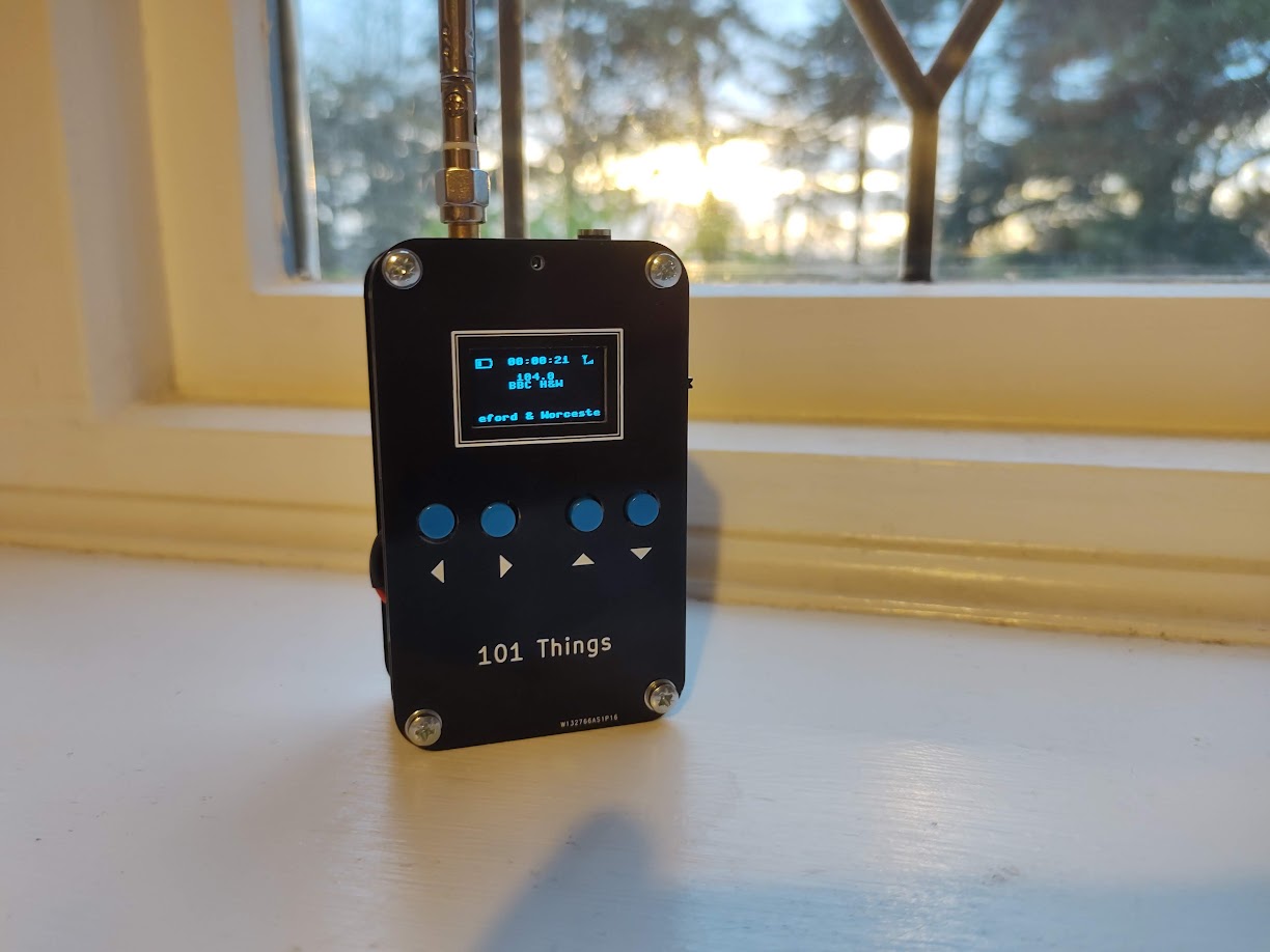
I decided to go for a simple, portable, battery-powered device. I retrofitted the functionality to my usual Swiss-Army-PCB encloser which I used in the guitar multi-effects unit and the power and SWR meter.
I wanted something that could run on batteries, with a small audio amplifier and speaker.

Parts List
Most parts are commonly available and could be purchased from multiple sources, but I have included links to some example components.
3x TPA2012D
5x 10uF ceramic capacitor X7R 0805
3x 1uF ceramic capacitor X7R 0805
1x 100nF ceramic capacitor X7R 0805
1x resistor 10R 0805
2x resistor 1K 0805
2x resistor 100K 0805
1x battery holder 2xAA or 2xAAA
1x speaker 4-ohm/8-ohm
PSU Noise
When I first built the radio, I powered both the RDA5807M and the Pi-Pico directly from 2xAA batteries. This worked quite well, but there were a couple of downsides to this approach.
The first issue was that noise from the pico reduced the performance of the FM receiver so that some of the weaker stations could no longer be received.
The second was that the voltage range of the RDA5807 is quite narrow from 2.7v to 3.3v. 2xNiMH cells should produce 2.4v when charged, reducing to 2.0v when discharged, in practice the device seemed to work with 2 AA NiMH batteries until they were almost completely discharged, but it would be nice to have the flexibility to use 2 or 3 NiMH or alkaline cells. This would need a voltage range from 2V to 4.5V. Another nice option would be to use a lithium polymer cell which might output 4.2V when charged and 3.4V when discharged. The Pi-Pico has a nice built-in switching regulator that can run on 1.8V to 5.5V, and efficiently produces a 3.3V output. If we could filter the 3.3v supply well enough to power the RDA5807M, this configuration would allow any of these battery combinations, while keeping power loss to a minimum.
Some better supply filtering was needed. I tried this circuit using a ferrite, resistor and capacitors.
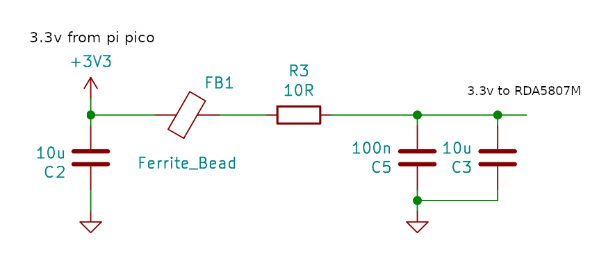
Adding the filter to the 3.3V output from the Pi-Pico did the trick. When the RDA5807M was able to receive even the weaker stations using the filtered supply.
User Interface
I was looking for something compact, low-power and inexpensive so I stuck with the usual SSD1306 OLED display. Fortunately, MicroPython has inbuild support for this type of display which helps to keep the development simple. I could have shared the I2C bus between the RDA5807M and the SSD1306, but I’m not doing much else with the Pi-Pico and I have plenty of spare IO so I used a separate bus. A few tactile push buttons are all that is needed to control the device.
MicroPython provides a flash-based file system so it is quite easy to store the settings by writing them to a file. This is certainly a lot easier than writing to Flash using the C/C++ SDK.
def load_settings():

    """ Load settings from a file in Flash on power-up """

    #default settings if no file present
    settings = {
        "volume" : 0,
        "mute" : False,
        "frequency_MHz" : 88
    }

    try:
        with open("settings.txt") as input_file:
            for line in input_file:
                key, value = line.split(":")
                key = key.strip()
                value = value.strip()
                settings[key] = value
    except OSError:
        pass

    return settings

def save_settings(settings):

    """ Save settings to a file when a change is made """

    with open("settings.txt", 'w') as output_file:
        for key, value in settings.items():
            line = "%s:%s\n"%(key, value)
            output_file.write(line)
Battery Monitor
In the Pi-Pico, VSYS (the battery input in our case) is permanently connected to one of the 5 ADC channels via a potential divider. This makes it very easy to track the battery voltage. I used a very simple smoothing filter to remove measurement noise.
#The ADC pin needs to be configured at power-up
adcpin = machine.Pin(29, machine.Pin.IN)

...

#read battery voltage
analogIn = ADC(3)
batt_voltage = analogIn.read_u16() * 3.0 * 3.3 / 65536
average_batt_voltage = (0.6 * average_batt_voltage) + (0.4 * batt_voltage)
Once we know the battery voltage, we can convert this into a battery level that can be drawn on the display. The battery level scale is from 0 to 10 with zero representing a flat battery and 10 representing a full one. The voltage of a full and flat battery depends on the battery chemistry.
# Values could be adjusted for different chemistry
# based on 2 AA cell
batt_voltage_max = 3.0
batt_voltage_min = 2.0

# based on 3 AA cell
#batt_voltage_max = 4.5
#batt_voltage_min = 3.0

# based on 1 3.7/4.2v Lithium Polymer cell
#batt_voltage_max = 4.2
#batt_voltage_min = 3.4

if average_batt_voltage > batt_voltage_max:
    batt_level = 10
elif average_batt_voltage < batt_voltage_min:
    batt_level = 0
else:
    batt_level = (average_batt_voltage - batt_voltage_min) / (batt_voltage_max - batt_voltage_min)
    batt_level = round(batt_level * 10.0)
Signal Strength Indicator
The RDA5807M provides an RSSI monitor indicating the signal strength. The rda7805.get_signal_strength() method returns a signal strength using a logarithmic scale from 0 to 7. The example code represents this as a signal strength icon which it draws on the screen.
def draw_signal_strength(display, radio):

    """ Draw a signal strength icon on screen. Queries radio's RSSI. """

    x = 110
    y = 0
    display.line(x+2,  y+0, x+2,  y+8, 1)
    display.line(x+0,  y+0, x+2,  y+4, 1)
    display.line(x+4,  y+0, x+2,  y+4, 1)

    level = radio.get_signal_strength()
    for i in range(level):
        display.line(x+4+(2*i),  y+8, x+4+(2*i),  y+8-i, 1)
RDS
The RDA5807M provides the ability to receive and decode RDS data. The datasheet for the device does seem to lack detail in this area. The RDS protocol supplies data in four blocks, the RDA5807M provides each of these blocks in a separate 16 bit registers RDSA/B/C/D. The protocol includes both data and parity bits which allows for bit errors to be either detected and corrected or just detected depending on how many bit errors are present. The RDA5807M does the error correction for us giving us only the data part of each block. The number of bit errors in blocks A and B can be determined by reading BLERA/B. As far as I can tell there is no way to tell how many bit errors are present in blocks C and D, so it doesn’t seem to be possible to completely avoid using corrupted data.
Experimentally, it seems that reading from RDSA/B/C/D is an atomic operation. So long as the registers are read in address order, the blocks always seem to relate to the same message. Also, it seems like polling the device for new messages every 10ms is more than sufficient to ensure that we don’t miss any of the received messages.
I included a simple RDS decoder, which only decodes station name, station text and time messages which are displayed on the screen.
Class-D Amplifier
Although the RDA5807M can drive headphones directly, it is nice to have a bit more power to drive a speaker. The LM386 might be the traditional choice, but I opted for the TPA2012D2. This class-D stereo amplifier is very efficient and can supply as much as 2.1W per channel into 4-ohm speakers. It is cheap and requires only a couple of supporting components, so really is ideal for a battery-powered application like this.
One potential downside of the TPA2012D2 is that the WQFN package isn’t particularly beginner-friendly. Fortunately, several ready-made modules such as this one are available.
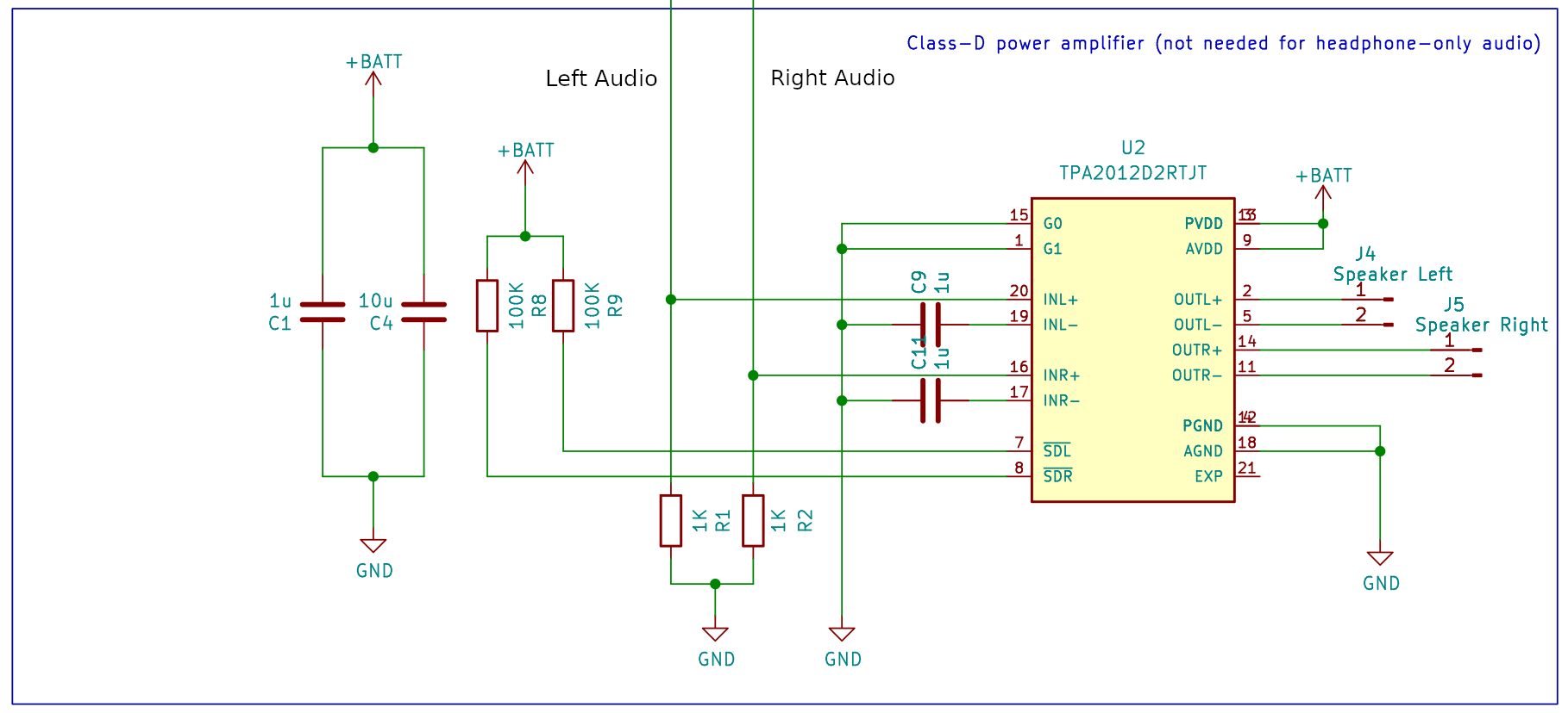
The IC has 2 inputs G0 and G1 that set the gain of the amplifier. In this application we don’t need much gain so I wired both these pins to ground giving the lowest possible (6dB) gain.
I opted for a tiny 8-ohm speaker, these tiny speakers sound pretty terrible unless they are sealed in an air-tight enclosure. Some kind of 3D-printed surround would have been ideal, but I went for a lower-tech solution and just used a bottle cap secured with adhesive. Although not Hi-Fi quality, once sealed in an enclosure I was quite happy with the quality. You can get miniature speakers that have a built-in enclosure. I would have taken this route but didn’t have the space in the enclosure.
A larger speaker (in a suitable enclosure) would give even better (and louder) audio, and would be worth considering if you have the space.
Antenna
The FM receiver is quite sensitive, and I found that the wire whip antenna was able to receive quite a few local stations. In the standalone receiver, I used an SMA connector for the antenna, this allows a compact telescopic antenna to be used for portable use while allowing a better external antenna to be used if necessary. It is possible to use the headphone cable as an antenna if suitable filtering is used, and the RDA5807 datasheet gives details on how to achieve this.
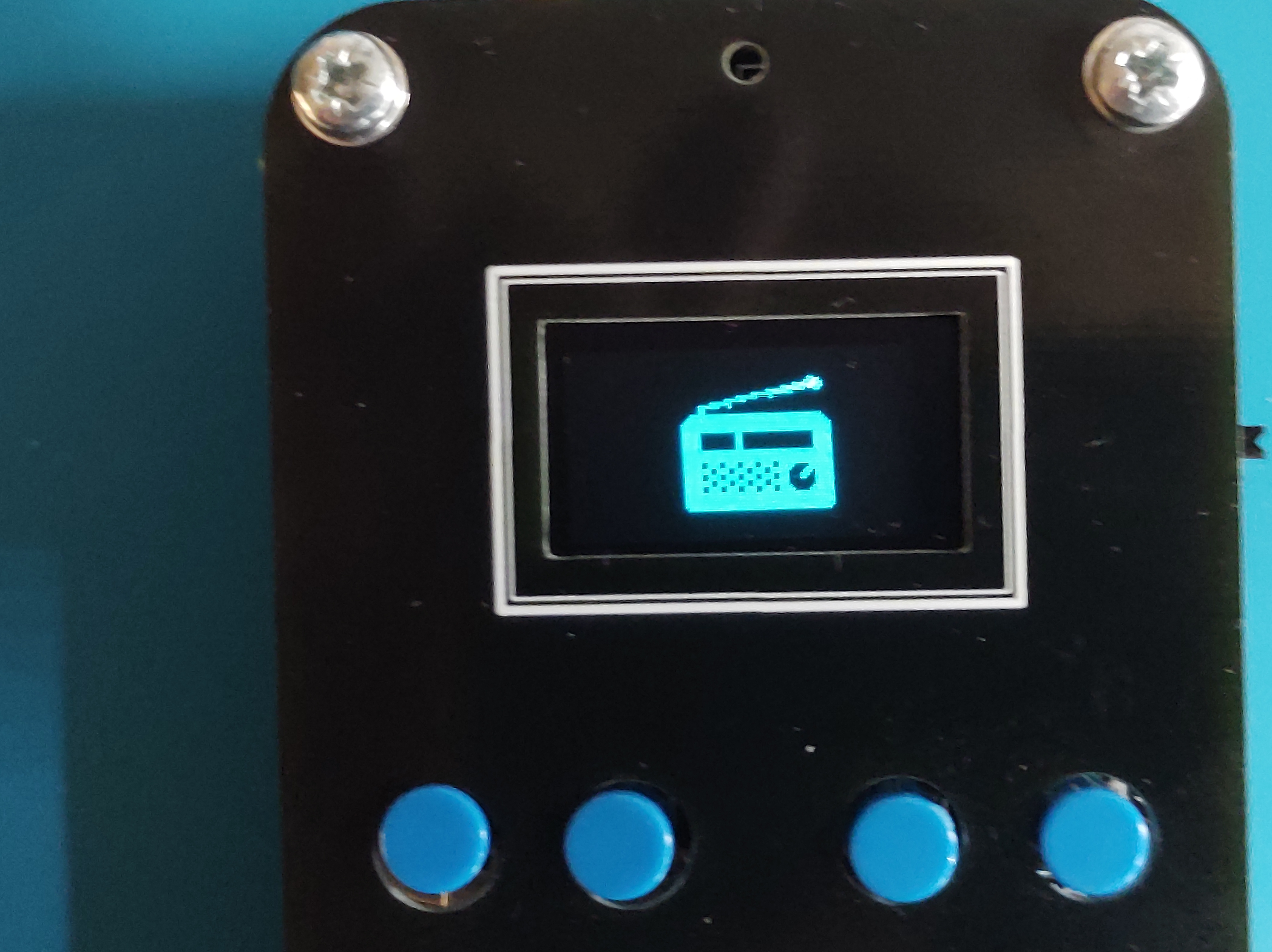
Splash Screen
For a bit of fun, I thought it might be interesting to play try displaying images on the OLED display. The MicroPython library for this display is based on the FrameBuffer class which provides drawing primitives but doesn’t have a way of loading an image from a file. The closest thing is the blit method that allows a frame buffer to be drawn on top of another. A FrameBuffer can also be passed a bytearray on construction, and it is simple enough to read this from a file.
def draw_image(display, filename):

    """ Load an image from flash into a framebuf object and display on screen """

    width = 128
    height = 64
    with open(filename, "br") as inf:
        data = inf.read(width * height // 8)
    fbuf = framebuf.FrameBuffer(bytearray(data), width, height, framebuf.MONO_HLSB)
    display.blit(fbuf, 0, 0, 0)
    display.show()
To limit the amount of processing that needs to be done in Python, I pre-process the image into a bytearray of the correct format using a Python script on a PC.
import imageio
import sys

input_file = sys.argv[1]
output_file = sys.argv[2]

im = imageio.imread(input_file)
h, w, c = im.shape

bytevals = []
for y in range(h):
  for i in range(w//8):
    byteval = 0
    for j in range(8):
      x = (i*8)+j
      byteval <<= 1
      if im[y][x][0] > 0:
        byteval |= 1
    bytevals.append(byteval)

with open(output_file, "wb") as outf:
  outf.write(bytes(bytevals))
The script uses the imageio library so can convert from most common image types. The image does need to have the correct height (in this case 128 pixels wide by 64 pixels high). The pixels in the image should be either black or white.

$ python image2fbuf.py radio.png radio.fbuf
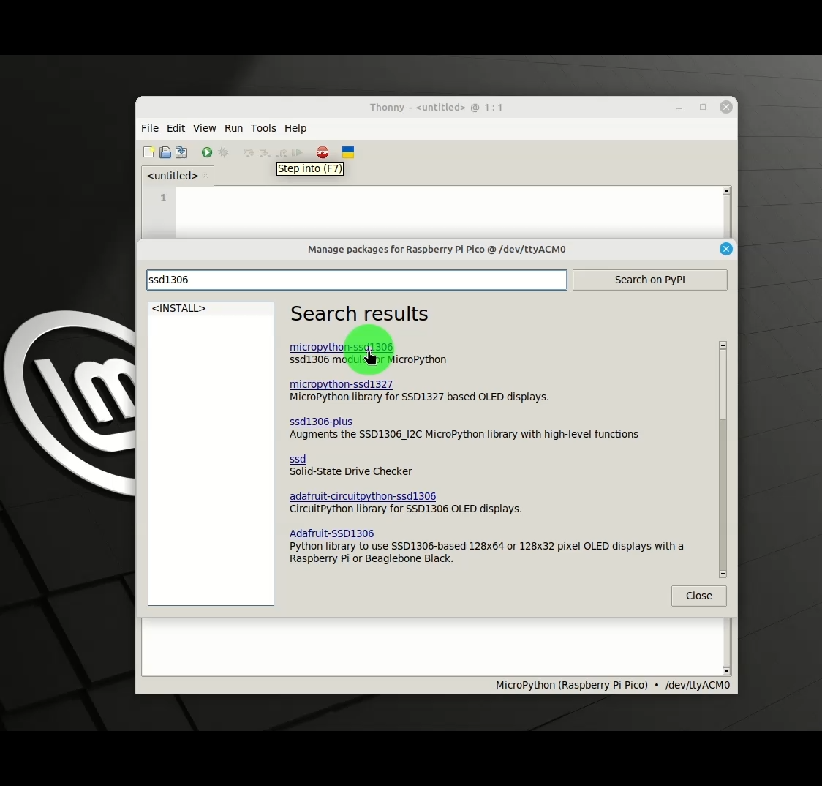
Installing the SSD1306 library
Assuming you have already installed Thonny and MicroPython, it is easy to install the SSD1306 library.
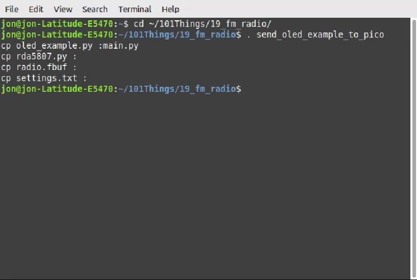
Loading the Python Project
I have written another pyboard.py based script send_oled_example_to_pico to download all the necessary files. This time the script sends the FrameBuffer image file along with the Python modules.
Testing
That’s it! A working FM radio receiver, using an RD5807M and a Pi-Pico programmed in MicroPython. The process was fairly simple, supplying the RDA5807 with a clean supply was probably the trickiest part of the project.
If you want to give it a go, you can find the code here: FM Radio Code
Useful Links
If you would like to support 101Things, buy me a coffee: https://ko-fi.com/101things