DIY Multi-Effect Guitar Unit: Affordable, Easy, and Versatile
Unlock Your Guitar’s Potential on a Budget
Are you a guitarist looking to explore a myriad of tones without breaking the bank? Look no further! Introducing our DIY Multi-Effect Guitar Unit — a cost-effective, straightforward solution for musicians who crave versatility without complexity.
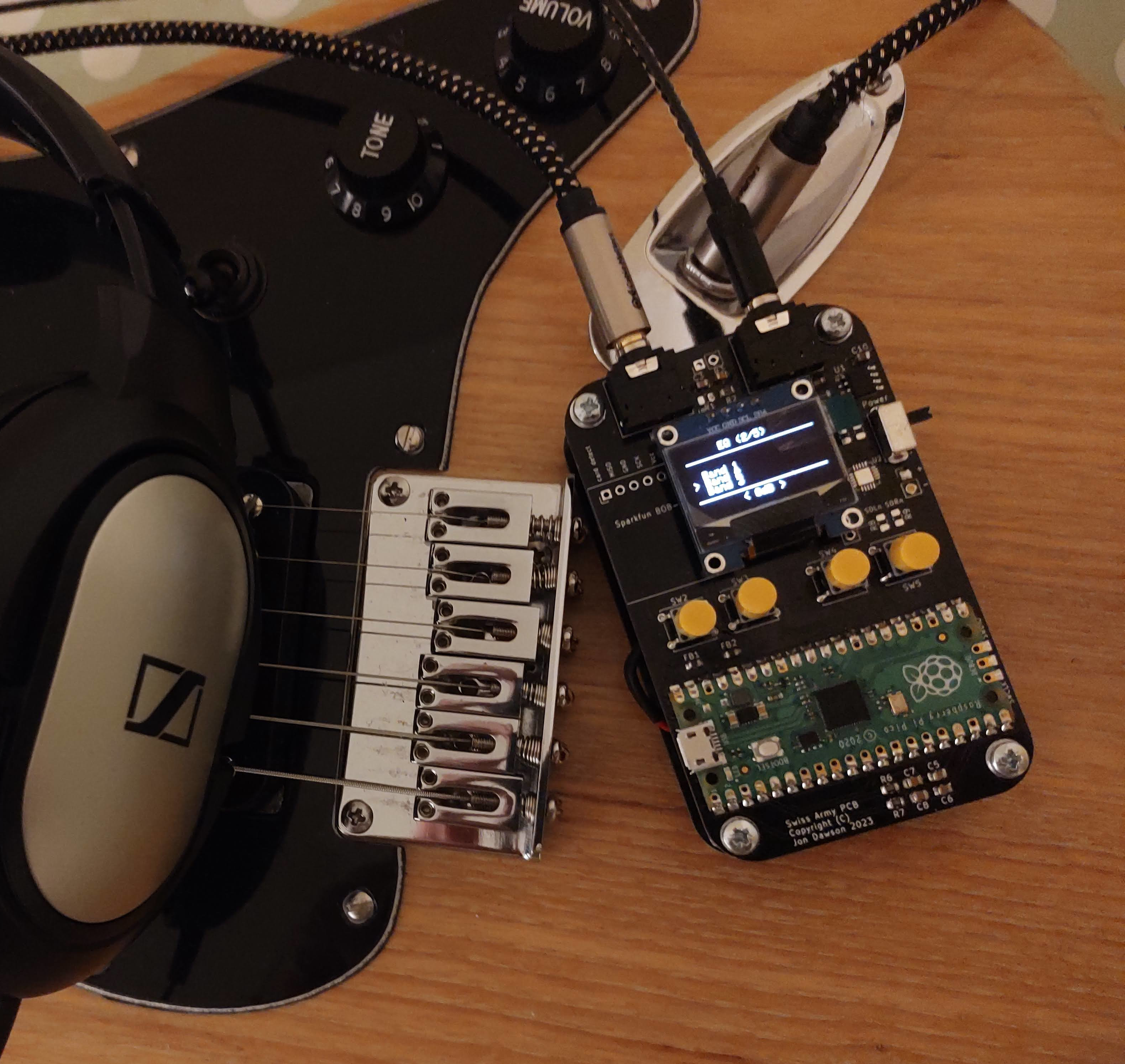
The DIY Multi-Effect Guitar Unit uses a minimalistic design that harnesses the power of the Raspberry Pi Pico and just a handful of additional components. With a total cost that amounts to just a few pounds, this project is not only budget-friendly but also remarkably simple to build. Regardless of your technical background, this unit is engineered to be accessible to anyone with a passion for music and a desire to experiment with their sound.
The secret to its affordability lies in the utilization of the Raspberry Pi Pico, a versatile microcontroller that serves as the brain of our DIY unit. Despite its modest cost, the Raspberry Pi Pico provides a robust platform for implementing a wide array of guitar effects usually found in much more expensive units.
So, whether you’re a seasoned electronics enthusiast or someone just dipping their toes into the world of DIY projects, the design allows you to create a feature-rich, multi-effect guitar unit without the headache of a convoluted assembly process or a hefty price tag.
Effects
The unit includes the most common effects, many of which can be used simultaneously.
5-Band Graphic Equalizer
Multiple Distortion Effects
Delay
Echo
Reverb
Chorus
Flanger
Phaser
Tremolo
Vibrato
Multiple Patch Memories
Firmware
In this article, I have gone into quite a bit of detail about how this works, which may be quite heavy going. Don’t let that put you off though, the circuit is quite simple and there’s a pre-built software image too, ready to download over USB.
PCB
I have put together a general-purpose PCB for audio-based Pi Pico Projects. This PCB only needs a few modifications to make the guitar effects unit.
Hardware Overview

Signal Path Amplification
The signal processing in our DIY Multi-Effect Guitar Pedal begins with a non-inverting amplifier with a high input impedance to avoid interference with the guitar’s natural tone. This amplifier offers 20dB of gain, strengthening the input signal for subsequent processing.
Analog-to-Digital Conversion (ADC)
After amplification, the signal enters the built-in Analog-to-Digital Converter (ADC), providing a resolution of 12 bits. Operating at a sampling rate of 320 kHz, the ADC captures the intricacies of the guitar output with precision.
Oversampling for Enhanced Signal Quality
To further enhance signal quality, the design incorporates a 16x oversampling technique. This technique adds an additional 2 bits to the Signal-to-Noise Ratio (SNR) and helps minimize aliasing effects. Oversampling at a higher rate than strictly necessary aids in reducing unwanted artefacts and contributes to the overall clarity of the processed sound.
PWM Audio
A Pulse Width Modulated (PWM) digital IO pin is used to output the audio. The PWM is configured to provide a 12-bit audio output. After the oversampling stage, the signal is directed through a first-order low-pass filter designed to eliminate any residual switching waveforms. This crucial filtering step ensures a cleaner output signal, free from unwanted artefacts and interference.
Given the crude nature of the PWM audio output, the quality of the audio is surprisingly good. The PWM signal is strong enough to drive headphones directly. The unit could be used as a headphone practice amplifier, or it could be integrated into an effects pedal, or even into a guitar amplifier.
User Interface
There isn’t anything particularly unusual about the user interface. A 128x64 OLED display uses an ssd1306-based I2C interface. These are fairly ubiquitous these days and have replaced the HD44780 as the go-to cheap/simple display. The The I2C interface certainly helps reduce the pin count. Cost is a key driver, so I have combined this with a few tactile push buttons to build a menu-driven interface.
Software Overview
One reason why we can achieve such simplicity in hardware is by consolidating all the functionality into the software. The Raspberry Pi Pico boasts a dual-core ARM processor, with each core operating at 120MHz. This speed is quite impressive for a microcontroller in this price range and is more than capable of handling audio processing tasks. However, memory and CPU resources remain relatively limited. As the Pi Pico lacks a Floating Point Unit, the design exclusively employs fixed-point arithmetic in the signal path. This approach provides us with additional headroom and allows for the integration of a greater number of effects.

The signal path is divided into 5 main functional blocks:
DC removal and preamplifier
5-Band Graphic Equaliser
Waveshaping (distortion)
Delay (delay, echo, reverb)
Modulation (Chorus, Phaser, Flanger, Tremolo, Vibrato)
Graphic Equaliser
For my first attempt at a graphic equalizer, I used a bank of 5 filters, each covering a portion of the spectrum. I opted for IIR filters, known for their efficiency. The approach worked quite well when processing some test audio on a laptop, but it couldn’t keep up on the Pi Pico. This is probably because I used a floating-point implementation. I considered converting this to a fixed-point implementation, but designing stable IIR filters using fixed-point arithmetic can be fairly tricky.
In the final solution, I used the Fast Fourier Transform (FFT) algorithm to perform the filtering in the frequency domain. Although the process of converting from the time domain to the frequency domain and back again is complex, the filtering operation is much simpler in the frequency domain, leading to an overall improvement for reasonably large filters.
The data is broken down into overlapping chunks of 64 samples. Each chunk is windowed using a Hann window to reduce spectral leakage. Subsequently, each chunk is transformed into the frequency domain using the FFT function, separating the signal into 32 frequency bins. Each bin can then be scaled according to a gain value before being transformed back to the time domain using an inverse FFT.
Graphic equalizer bands are typically sized on a logarithmic scale. The first band uses a single frequency bin, the second uses 2, and the subsequent bands use 4, 8, and 18, respectively. This logarithmic scaling ensures that each band covers the same number of musical tones.
Building Blocks
Two building blocks are used throughout the software, the Low Frequency Oscillator (LFO), and the tapped delay line. The implementation of these basic building blocks is very simple, but they can be combined to produce a wide variety of effects.
FixedPoint lfo ::get_sample(uint16_t frequency_steps, FixedPoint amplitude) {
  FixedPoint sample = sin_table[p >> 6] * amplitude; // 10 MSBs (16-10 = 6)
  p += frequency_steps;
  return sample;
}
The LFO is a very precisely controlled oscillator. The first part is the phase-accumulator p, which is simply a counter. The phase accumulator is scaled so that the whole range of a 16-bit number represents a full cycle of the waveform. For each sample, we add a fixed amount frequency_steps to the phase-accumulator. The higher the frequency, the more phase we add, and the more frequently the phase accumulator overflows. The maximum value of a 16-bit number is 65535, with a 20kHz sample rate that gives a range of 0-10kHz with a resolution of 0.3 Hz. We can convert from Hz to frequency steps using this function.
uint16_t frequency_Hz_to_steps(float frequency_Hz) {
  return static_cast<uint32_t>(65536 * frequency_Hz / audio_sample_rate_Hz);
}
We can convert the phase into a sinusoidal waveform using a lookup table. The lookup table has 1024 entries, so we only need the 10 highest bits.
The delay line class is implemented using circular buffers. For simplicity, I have chosen a length which is a power-of-2, this means that I can implement a circular pointer using only an and operation.
The input_sample function adds a new sample to the delay line, and increments the input pointer effectively moving all the samples one place along the delay line. The tap function extracts a sample from any position along the delay line.
void delay_line ::input_sample(FixedPoint sample) {
  buffer[input_pointer] = sample;
  input_pointer = (input_pointer + 1) & 0xfff;
}

FixedPoint delay_line ::tap(uint16_t delay) {
  return buffer[(input_pointer - delay + 1) & 0xfff];
}
Waveshaper
Waveshapers are essential tools for crafting the distinctive distortion effects heard in electric guitar playing. Typically used in the form of distortion pedals or software plugins, waveshapers manipulate the guitar’s audio waveform by introducing non-linearities, achieved through techniques like soft clipping. As the guitar signal passes through, these devices alter the waveform by compressing or clipping specific parts, resulting in harmonically rich overtones and a gritty texture.

The cubic, quadratic and fuzz waveshapers apply increasingly hard clipping, resulting in progressively “squarer” waveform containing more harmonics.

There are a few more experimental waveshapers that create rich even harmonics. The half-wave and full-wave rectifiers introduce a frequency-doubling effect by removing or reusing the negative half-wave. The foldback distortion creates additional harmonics by folding the clipped portion of the signal back on itself.

The shaping functions have an interesting effect on the signal.

Delay Effects
The effects unit includes three types of delay-based effects. Delay is a guitar effect that repeats the input signal with a time delay, creating a series of distinct echoes. Echo is similar but often refers specifically to a more pronounced, distinct repetition of the original sound. Reverb simulates the acoustic characteristics of physical spaces, adding a sense of space and depth to the guitar signal by blending numerous reflections of the sound.
Delay

The simplest delay effect adds a single delayed version of the signal to the input. We can vary the size of the delayed signal relative to the original signal.
delay_line.input_sample(sample);
sample = sample + delay_line.tap(delay_ms * samples_per_ms) * delay_mix;
Echo

The simple delay produces a single echo. By adding simple feedback we can get multiple, repeated echos which reduce in amplitude with each repetition.
delay = delay_line1.tap(delay_ms * samples_per_ms);
mixed = sample + delay * delay_feedback;
delay_line.input_sample(mixed);
sample = sample + (delay * delay_mix);
Reverb

While the echo effect is simple to produce, it doesn’t sound like the natural reverberations that occur in real spaces. It turns out that it is quite hard to make a natural-sounding reverb.
A natural reverberation has thousands of echoes that follow many complicated paths from the source. In a natural reverberation, the echos are so dense that you can’t distinguish individual echos.
We could increase the density of the echos by reducing the delay in the echo effect, but if we do this the constructive and destructive interference causes the system to behave like a comb filter which with notches at many frequencies which tends to colour the tone of the signal rather than providing a natural sounding echo.

This is one of the best articles I have found on the subject. Signal Smith Blog I have tried to use some of these ideas to build a very minimal version.
This design uses a feedback delay network, the signal passes through several delay lines of different lengths, the delayed signals are then mixed together using a matrix resulting in much denser and more random-sounding echos.
//delay Lines
delays[0] = delay_line1.tap(150 * samples_per_ms);
delays[1] = delay_line2.tap(160 * samples_per_ms);
delays[2] = delay_line3.tap(170 * samples_per_ms);
delays[3] = delay_line4.tap(180 * samples_per_ms);

//feedback matrix
for (int i = 0; i < num_delays; ++i) {
  mixed[i] = delays[i];
  sum = sum + mixed[i];
}
sum = sum * FixedPoint::from_float(-0.5);
for (int i = 0; i < num_delays; ++i) {
  mixed[i] = mixed[i] + sum;
}

//feedback gain
for (int i = 0; i < num_delays; ++i) {
  mixed[i] = sample + mixed[i] * delay_feedback;
}

delay_line1.input_sample(mixed[0]);
delay_line2.input_sample(mixed[1]);
delay_line3.input_sample(mixed[2]);
delay_line4.input_sample(mixed[3]);

sample = sample + (delays[0] * delay_mix);
There is still room for improvement here, we could make a better more natural-sounding reverb by increasing the number of delay lines. The design would also benefit from a diffuser stage.
Modulation Effects
In the realm of guitar effects, modulation effects play a pivotal role in shaping the sonic landscape, adding depth, movement, and character to your playing. These effects manipulate the audio signal in real time, creating dynamic variations that go beyond the static nature of traditional distortion or delay effects.
Tremolo
Tremolo modulates the volume of the signal at a rhythmic pace, creating a pulsating effect. It’s a classic effect that can range from subtle rhythmic pulsing to more pronounced amplitude modulation. Tremolo can add a vintage, surf-rock vibe or a dynamic rhythmic element to your playing.

Vibrato
Vibrato, often confused with tremolo, modulates the pitch of the signal. It introduces slight variations in pitch, simulating the natural vibrato produced by a guitarist’s finger movements. Vibrato adds expressiveness and warmth to sustained notes, making it a popular choice for lead guitar playing.

Flanger
Similar to a chorus, a flanger duplicates the signal but introduces a short delay that varies over time. This creates a sweeping, jet-like sound characterized by a distinctive whooshing effect. Flangers are commonly used to add a sense of motion and intensity to guitar solos or rhythm parts.

Chorus
Chorus imparts a lush and shimmering quality to your sound by duplicating the signal, introducing slight pitch and time variations, and blending it with the original. The result is akin to a choir of subtly detuned voices, producing a thicker, more expansive sound that simulates the effect of multiple instruments playing in unison.

Phaser
A phaser effect alters the phase of the input signal, creating a distinctive swirling or sweeping sound. By splitting the signal and modulating the phase relationship between the two paths, phasers produce a rich, evolving texture often associated with spacey or psychedelic tones.
Useful Links
If you would like to support 101Things, buy me a coffee: https://ko-fi.com/101things